MACS Matchmaker
The MACS Matchmaker consists of the following main parts:
- MACS Sampler — Liquid handler unit for automatic sample injection.
- MACS Matchmaker — FM instrument with three integrated cameras: chip surface, mologram recognition, and coupling.
- FM Readout
- Diffractometric channels — Measures specific binding on functionalized molograms.
- Refractometric channels — Measures bulk refractive index changes; used for referencing and drift correction.
- Fluorescent channel — Measures fluorescent signals at an excitation wavelength of 663 nm.
- Fluidic heads
- Closed — For automated sample injection from MACS Sampler to MACS Matchmaker.
- Open — For cell assays and manual pipetting.
- Chips — Consumable chips used in the instrument.
Instrument Operation
MACS Matchmaker Components
The MACS Matchmaker is a benchtop reader unit. It contains the Liquid module and uses two lasers: one at 784 ± 5 nm (Molography) and one at 663 ± 5 nm (Fluorescence).
Status LEDs
MACS Matchmaker Status LED
The MACS Matchmaker has a status LED at the front of the reader unit. Colour says what state it is in and the blink rate separates the states that share a colour — among them the fast cyan blink the instrument shows while it runs its post-experiment wash. Reading the Status Light lists every combination.
Degasser Status LED
The running buffer is pumped through a degasser before it reaches the reader unit. The degasser status LED is located above the syringe pump in the liquid module and is visible when the lid is open. On supported instruments, the degasser switches off after 60 minutes without a measurement or use of the liquid handler. It switches back on when the liquid handler is used again or a measurement starts.
| Color | Status |
|---|---|
| Green | Degasser operates normally |
| Red | Insufficient vacuum for degassing — contact lino Biotech Support |
MACS Sampler Status LED
| Color | Frequency | Status |
|---|---|---|
| Green | Static | Instrument is operating normally |
| Red | Blinking | Instrument error |
Compatible Liquids
The liquids the instrument can run — the aqueous pH range, the tested organic solvents, and the maximum sample particle size and temperature — are the operating limits listed under Operating Limits on Safety & Compliance, alongside the hazards and disposal guidance for anything you put through the instrument.
Run a buffer suited to the interaction under study, and dilute samples and immobilization reagents into that same running buffer unless a protocol specifies otherwise. The reader degasses the running buffer automatically before it reaches the flow chamber, so no separate degassing step is needed. Whatever the buffer, everything in it must stay fully in solution: a component that precipitates in the lines can clog the microfluidic tubing, so keep additives below their solubility limit and filter where needed (see Sample Preparation below).
Sample Preparation
- Ensure the total injection volume is accounted for. The software automatically selects the best matching injection mode based on the programmed sample injection parameters.
- Add the dead volume of the respective vial to the volume reserved for injections (see dead volumes in the consumables section below).
- Do not fill vials or wells to the edge. Otherwise sample will be forced into the air needle, risking cross-contamination and soiling the needles.
- Filtering samples with a 0.2 µm filter will considerably reduce the risk of clogging. Ensure appropriate filter material is used for your sample type.
- If the required sample volume exceeds the vial capacity, aliquot the sample into several vials.
Recommended Seal Types
| Sample container | Seal type |
|---|---|
| Standard (low) well plates | Sealing tape |
| Deep well plates | Pierceable cap mats (pre-slit or silicon) or sealing tape |
| Vials | Standard septa (thin types). Do not use vials with hard caps not designed for piercing by an injection needle. |
MACS Sampler (Accessory)
The MACS Sampler (Order number 130-137-262) is a high throughput autosampler with an integrated cooling module that allows sample cooling down to 4 °C.
- Switching On: Switch on the MACS Sampler before switching on the MACS Matchmaker.
- Cooling: Built-in Peltier cooling, range +4 °C to ambient −3 °C. Configurable from +4 °C to +22 °C in the software. Fit the insulating insert whenever the tray is cooled; see Temperature Controls.
- Capacity: Supports 96-well plates, 384-well plates, and racks for 48 vials (300 µL) and 12 vials (10 mL). Maximum plate/vial height: 47 mm (including septa or cap mat).
- Loop volume: 500 µL.
- Dead volumes: 300 µL glass microvial: 30 µL dead volume. 2 mL glass vial: 300 µL dead volume.
Full Loop Injection
A full-loop injection fills the entire sample loop of the autosampler. The system uses Full Loop Injection mode when you select it for a command, or when the pickup volume equals the full-loop volume of twice the loop plus the 30 µL flush:
- The contact time is automatically calculated based on the loop volume and the specified flow rate.
- The contact time field becomes read-only — users only need to specify the flow rate.
- This mode ensures maximum sample utilization when working with larger injection volumes.
Syringe Pump Refill
There are two separate fluidic paths, and this section is about one of them. The MACS Matchmaker's own path runs from the buffer bottle through its syringe pump and the flow cell to waste; it is what carries running buffer over the chip. The MACS Sampler's path is upstream of that — its own syringe, needle and sample loop aspirate from a vial and deliver the plug into the Matchmaker's stream. The pump described below is the Matchmaker's.
During a measurement the pump stops short of the mechanical limit, keeping a fixed usable-volume margin of 4% of the stroke — on a 2500 µL syringe, 100 µL, so a refill settles at 2400 µL. The margin is what a measurement draws on, and it also gives the refill somewhere to overshoot into.
That overshoot is the return steps: the plunger draws a little past the target and settles back, taking up mechanical backlash so the final position is repeatable. It is much the smaller of the two — 0.6% of the stroke against the margin's 4% — and the two reservations do not add up. The pump keeps whichever is larger, because the margin is already big enough to absorb the overshoot.
Advantages:
- More repeatable refill volumes and a lower risk of pulling in air.
- The controlled overshoot relieves mechanical backlash and negative pressure at the end of the draw, and lands inside the margin rather than against a hard stop.
For standard liquid handler operations (fill, prime, flush) the syringe is always completely refilled to the mechanical limit.
Instrument Setup Workflow
Each stage below has a visible result. Confirm it before moving on — a stage that reports success on a chip that is not ready costs a full measurement.
- Preparation. Waste bottles empty, running buffer attached, flow chamber inserted. The sensor loading bay opens with the button in front of it.
- Liquid handler preparation. Prime the pump, the MACS Sampler, and the chip. Watch the fluidic connections during priming: any visible liquid at a fitting means the path leaks and the run will lose sample.
- Reader preparation. All status indicators reach "Success". Coupling is symmetric across all eight channels, and the Fourier aperture shows a symmetric intensity distribution with the molographic focus inside it. Fourier and surface focusing show live camera previews during optimization. On Sirius chips, the final Y refinement aligns the left SiO₂ side peak to its calibrated offset. During intensity optimization and reference alignment, the preview includes frames captured while the motor stops at the end of a sweep. On Sirius and Callisto chips, reference alignment selects an exposure for the surrounding pattern on each axis and keeps it fixed during that sweep. X alignment must pass its symmetry, illumination, and reference-quality checks before Y alignment starts. Reference checks exclude detected interfering image structure and patterns too weak to distinguish from noise before movement. Illumination checks include all reference regions. At least two usable references are required, and the same references are checked throughout each sweep. If their quality is lost and alignment cannot succeed, the axis returns to its position at the start of that alignment stage. Each axis is checked immediately after its own sweep; preparation stops if either axis fails. After three consecutive delayed frames, previews switch to requesting one image at a time while preserving image detail. The last image stays visible between updates. Close and reopen the preview to resume continuous streaming after the connection improves. The final image remains visible after completion. Repeat an individual failed step with its Reoptimize button; manual coupling and XY-stage adjustment are described under Manual Chip Preparation.
- Bubble check. The surface image and the molographic image are both visible here. Prime the chip once or twice to clear air bubbles from the surface; if they persist, take the chip out and reassemble it in the flow chamber.
- Mologram recognition. Run the check to confirm the molographic foci are found. Run it a second time if it fails, and prepare the reader again if it still does.
When the flow chamber selected on the Prepare page differs from the one saved in the experiment plan, the page shows a warning. Its association flow rates are not recalculated; update and save the experiment plan so it carries the defaults for the chamber actually in use.
Reading the Status Light
The light on the instrument reports what it is doing without anyone having to look at a screen. Colour says what state it is in; whether it blinks, and how fast, separates the states that share a colour.
| Light | State | What it means |
|---|---|---|
| Blue, blinking slowly | Preparation | Coming up, or being made ready for a measurement. |
| Blue, steady | Ready | Idle and available to start a measurement. |
| Blue, blinking | Executing a task | Carrying out a single instruction — a wash, a refill, a stage move — outside a measurement. |
| Green, steady | Measuring | An experiment is running. Leave the instrument alone. |
| Cyan, blinking fast | Post-experiment wash | The automatic wash after the last measurement of a batch. The instrument refuses to start anything until it finishes. |
| Red, steady | Error | The run failed. Anything left in the schedule has been discarded; see Troubleshooting. |
| Off | Switching off | Shutting down, or powered down. |
Scheduling the Next Measurement
While a measurement is running, you can line up the next ones on the same chip. When the current measurement finishes, the instrument starts the next scheduled one by itself, so consecutive measurements — for example an overnight series — run without anyone at the instrument.
Where to find it
Scheduling controls appear only while a measurement is running. On an idle instrument the same places show the normal controls for starting a measurement, and there is nothing to schedule onto.
- Plan, experiment list: in the Actions column, the Run button of each experiment is replaced by a Schedule Measurement button (a stacked-squares icon with a plus sign). Hover over it to see its name.
- Perform: the button in the top bar reads Schedule Measurement instead of New Measurement. Click it, select the experiment, and click Schedule Measurement again.
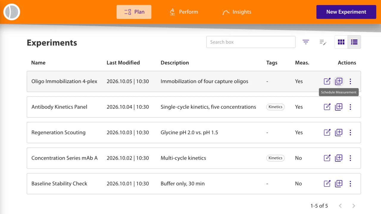
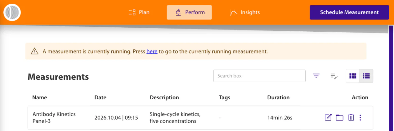
Once at least one measurement is waiting, the banner on the Perform page shows how many and offers View Schedule. The schedule lists each waiting measurement with its estimated start and end time, and a scheduled measurement can be removed there before it starts.
Setting up a scheduled measurement
Both entry points open the Schedule Measurement dialog. Give the measurement a name, then use Select Flow Channel to choose the channel it runs on. The chip, flow chamber and well plate type are those of the running measurement; if the experiment plan specifies different ones, the dialog warns and scheduling is not possible.
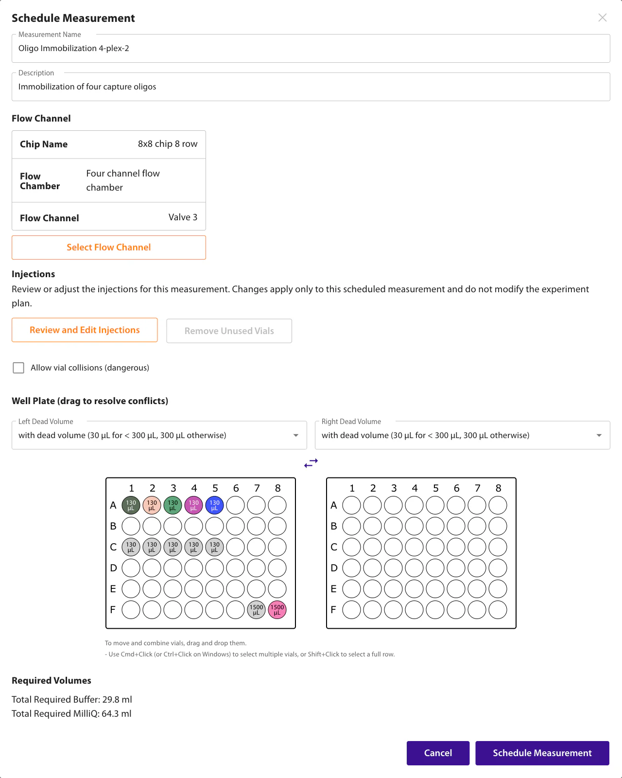
Use Review and Edit Injections to adjust the injections and vial assignments of this measurement. After removing injections, use Remove Unused Vials to clear their vials from the scheduled setup. Neither action modifies the saved experiment plan.
The well plate combines the vials of every measurement still to run; vials already in use are shown in grey and cannot be moved. If a vial of the new measurement sits on a position already in use, the collision is listed; drag the vial to a free position, or swap the left and right plates. Leave Allow vial collisions off unless the shared position really holds the right liquid for both measurements.
Required Volumes shows the running buffer and MilliQ still needed by the running measurement and everything queued after it; hover a total to see each measurement. The MilliQ total counts the sampler's washes, the transport liquid of pickup injections and the loop purge after each cropped injection. If the pump has a wash port and the post-experiment wash is on, it also counts that wash once, since the wash port draws from the same bottle. A 35% margin is added: a bottle that runs dry mid-run injects air.
How the schedule runs
The schedule is a queue, run strictly one at a time and only while something is already running. When a measurement finishes, the next one in the queue starts immediately with its own flow channel and injections.
Estimated runtimes include injection contact times, sample preparation, delivery, flushing and transitions between commands. Preparation time depends on the pickup volume and whether the sampler uses pickup, partial-loop or full-loop mode. The running estimate uses the remaining contact time of the active injection. Actual runtimes can differ because of syringe refills, early stopping, live edits or hardware delays; the final instrument wash is outside the estimate.
A failure empties the queue. If a measurement ends unsuccessfully, everything still waiting is discarded rather than run against a state nobody has checked, and the instrument goes to its error indication and washes. If a scheduled measurement cannot be started, the rest of the queue is discarded as well.
The wash runs once, at the end. A chained batch is not washed between measurements; the post-experiment wash runs when the queue empties. It is skipped for a run that made no injections, and needs both the auto-wash option and a configured wash port.
Image acquisition frequency
During a running measurement, expand the Images card and select the gear beside the collapse icon. Set the fluorescence, surface, and result-image intervals in measurement steps. An interval of 1 produces an image every step. Clear an image type's checkbox to turn it off; its interval field is cleared and disabled. Select the checkbox and enter an interval to enable it again. Save applies the settings to the current measurement. Cancel discards edits. These settings do not change the saved experiment plan or the continuous molographic signal acquisition.
Temperature Controls
Select the well-plate icon on the Autosampler card during measurement preparation or a running measurement to configure autosampler tray cooling. The icon is violet while it can be opened and grey while it cannot. When the measurement has injections, the Fluidics button on the Configurations card of measurement preparation opens the same settings. There is no Save button: a checkbox is saved when it is ticked, and the temperature when you leave its field. Saved settings take effect during the current measurement, while the Cooling during measurement option is fixed once the measurement has started. Select the thermometer icon on the Heater card during a running measurement to configure the stage heater.
Tray cooling starts from a set point of 15 °C. Below 16 °C the tray loses heat to the room faster than the element can remove it, so fit the insulating insert before asking for a lower set point — without it the tray settles above the value you entered rather than reaching it.
The measurement itself runs at ambient temperature: the reader does not hold the flow chamber at a fixed set point, and the stage heater is engaged only when an application needs a defined elevated temperature. Because association and dissociation rates — and the affinities derived from them — depend on temperature, keep the room temperature stable across a titration and note it with the result when comparing runs.
MACS Sampler Consumables
Below are the well plate and vial types used in our system along with their specifications.
12-Well Plates
- Dead Volume - 1200 µL
- 12-Well Plates for 22mm OD Vials by Spark Holland
- 10 mL Vials by Fisher Scientific
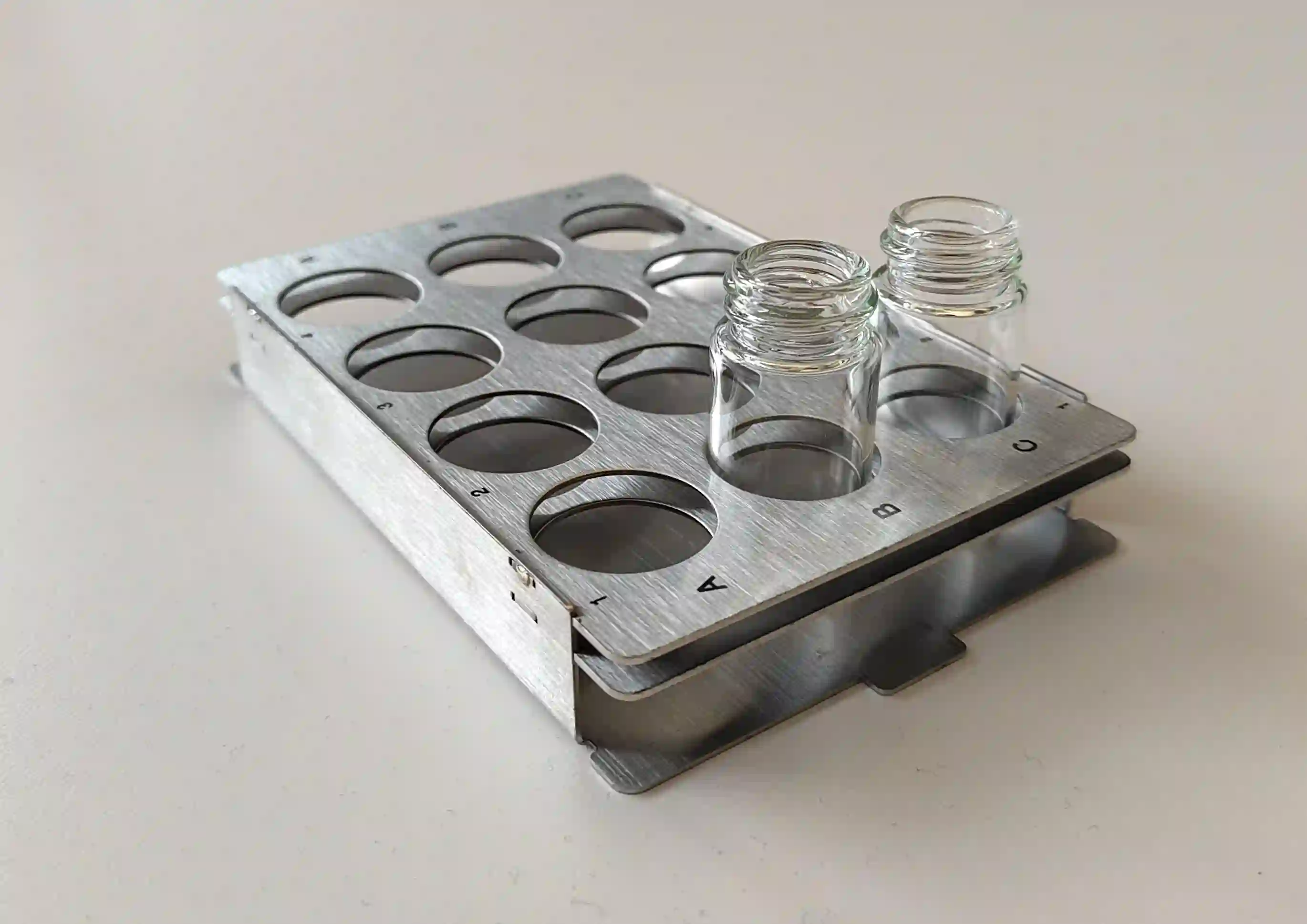
48-Well Plates
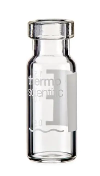
- 0.3 mL vials (right)
- Dead Volume - 30 µL
- 0.3 mL Vials by Thermo Fisher Scientific
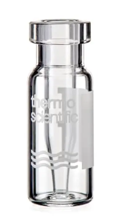
- 2 mL vials (left)
- Dead Volume - 300 µL
- 2 mL Vials by Thermo Fisher Scientific
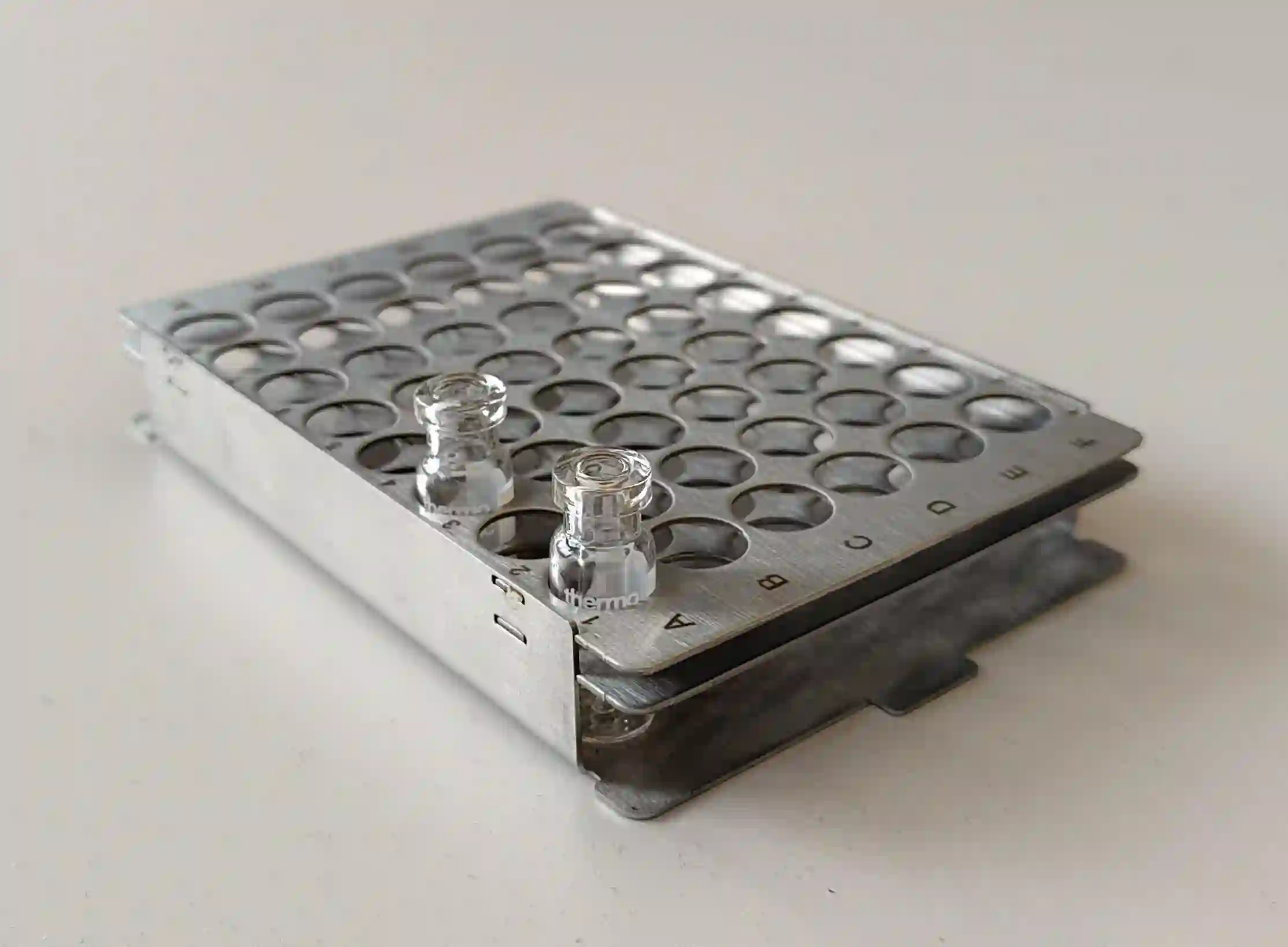
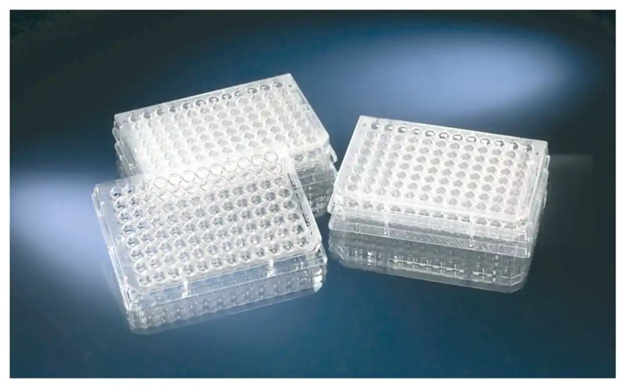
96-Well Plates (Low, V-shaped)
- Dead Volume - 4 µL
- 96-Conical Bottom Microwell Plates by Thermo Fisher Scientific
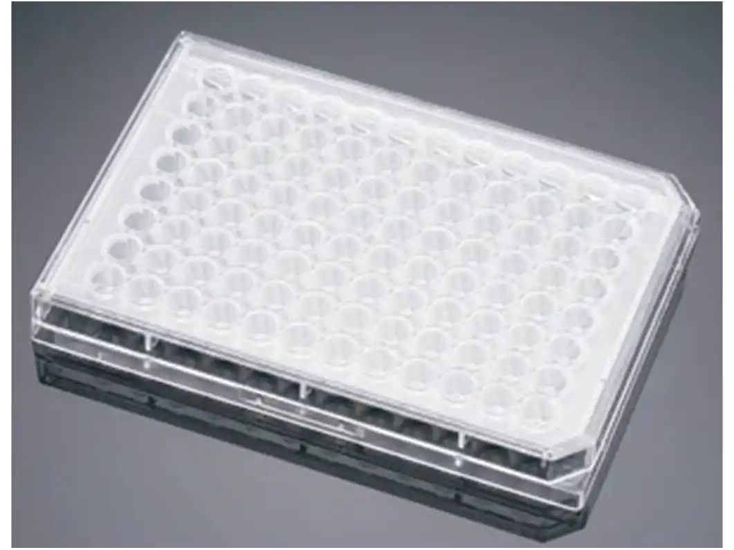
96-Well Plates (Low, U-shaped)
- Dead Volume - 8 µL
- 96-Well Plates, U-Shaped by Thermo Fisher Scientific
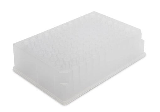
96-Well Plates (High, V-shaped)
- Dead Volume - 40 µL
- 96-Deep Well Plates, Square V-Bottom by Thermo Fisher Scientific
384-Well Plates (U-shaped)
- Dead Volume - 8 µL
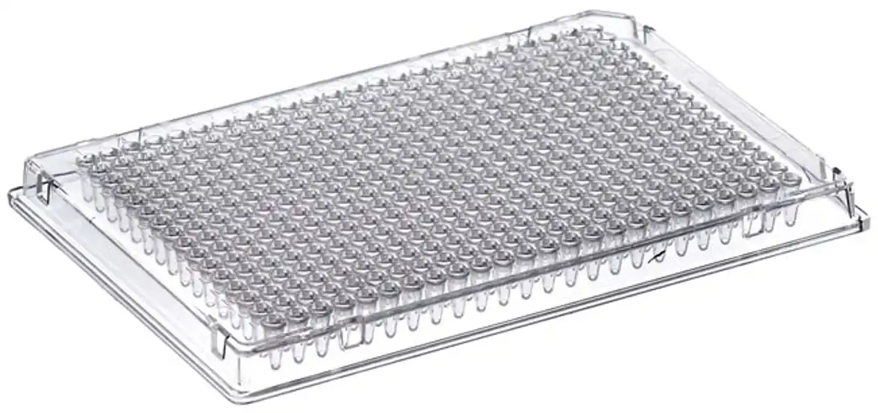
- 384-Well Microtiter Plates, Square U-Bottom by Thermo Fisher Scientific